
The short answer: when a 433 MHz remote works perfectly on the bench but becomes unreliable after installation, the transmitter is rarely the only thing to blame. In most cases the failure comes from one of four areas: the antenna is being detuned by metal, electrical noise is entering the receiver, the receiver supply is collapsing under load, or another RF source is occupying the channel.
I have seen all four faults described as “short range.” That description is understandable, but it sends troubleshooting in the wrong direction. A true range limit is usually repeatable: move farther away and the link gradually becomes less reliable. Interference and installation faults are less polite. They appear at certain times, around certain machines, or only when the controlled load switches.
First, decide what kind of failure you actually have
Before changing antennas or ordering a higher-power transmitter, watch the behavior. The pattern is often more useful than a signal-strength number.
Works nearby but not at the required distance: start with antenna position, enclosure material, polarization, and receiver sensitivity.
Works in the morning and fails later: suspect a nearby transmitter, LED driver, charger, inverter, or other equipment that operates on a schedule.
Receiver LED reacts, but the relay or machine does not: the RF link may be healthy. Check output mode, wiring, supply voltage, interlocks, and the load circuit.
Fails exactly when a motor, solenoid, or contactor operates: suspect conducted noise, voltage dip, or switching transients before blaming the radio.
Only fails with the enclosure closed: the antenna is probably too close to metal, shielding, wiring, or the PCB ground area.
This distinction matters. A stronger transmitter will not repair a receiver that resets every time its relay energizes, and a longer antenna will not cure noise travelling through the power leads.
A field test that gives useful answers
When I troubleshoot an intermittent wireless control, I use the same sequence every time. The aim is to change one condition at a time. Randomly moving wires, replacing batteries, and pressing the button repeatedly may make the system work, but it does not tell you why.
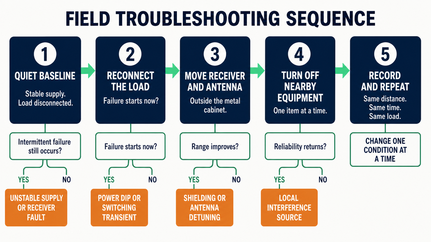
A repeatable test sequence separates power, shielding, antenna, and local-interference faults.
1. Build a quiet baseline
Power the receiver from a known stable supply, disconnect the real load, and test it in open space. Keep the receiver and antenna away from the control cabinet, mains wiring, laptop power supplies, and USB chargers. Test from several fixed distances and record ten or twenty commands at each point.
If the receiver is already unreliable in this condition, check the transmitter battery, pairing, frequency, antenna length, and receiver hardware. If it is stable, the installation is introducing the problem.
2. Reconnect the load without moving the radio
Reconnect the relay, solenoid, motor controller, or other load while leaving the receiver in the same position. If failures begin when the load switches, monitor the receiver supply at that exact moment. A multimeter may miss a brief dip, so an oscilloscope is better when one is available.
Also look for resets: a status LED restarting, a relay dropping out, or learned codes disappearing temporarily. Those are power-integrity symptoms, not RF-range symptoms.
3. Move only the receiver and antenna
Temporarily move the receiver outside the metal cabinet or extend the antenna through a proper insulated feed-through. Do not change the transmitter, supply, or software. A large improvement points to shielding, detuning, or poor antenna placement.
4. Switch nearby equipment off one item at a time
Common offenders include variable-frequency drives, inexpensive LED power supplies, battery chargers, switching power adapters, welding equipment, and other licence-free-band transmitters. Turn off one candidate, repeat the same test, and write down the result. If several devices are turned off together, you will not know which one mattered.
5. Repeat the test at the time the failure normally occurs
Interference is often intermittent because the interfering equipment is intermittent. A clean test at 10:00 does not disprove a problem reported at 18:00. Reproduce the operating schedule as closely as possible.
The antenna is part of the circuit, not a loose piece of wire
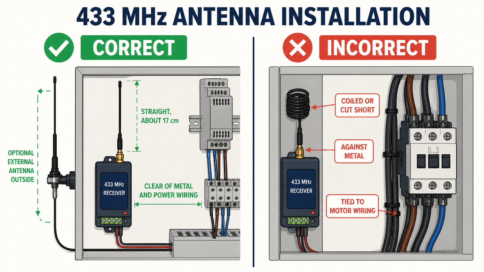
Keep the antenna straight and clear of metal and motor wiring; use an external antenna when the receiver is inside a metal enclosure.
At 433.92 MHz, a straight quarter-wave wire is roughly 17 cm long. That does not mean every receiver should be fitted with exactly 17 cm of any available wire; the PCB layout and antenna matching still matter. It does mean that folding the antenna into a tight loop, cutting it short to fit a box, or tying it against a wiring harness can seriously change performance.
For a typical wire antenna:
Keep it straight where possible.
Keep it away from metal panels, relay bodies, transformers, and large cable bundles.
Do not run it parallel and tight against mains or motor wiring.
Keep transmitter and receiver antennas in the same general orientation during testing.
For a metal enclosure, use a correctly designed external antenna and suitable feed-through rather than leaving the antenna inside the box.
More antenna is not automatically better. An arbitrary long wire can be poorly matched and collect more unwanted noise. Use the antenna arrangement recommended for the receiver, then solve placement before experimenting with length.
Noise reaches the receiver by two different paths
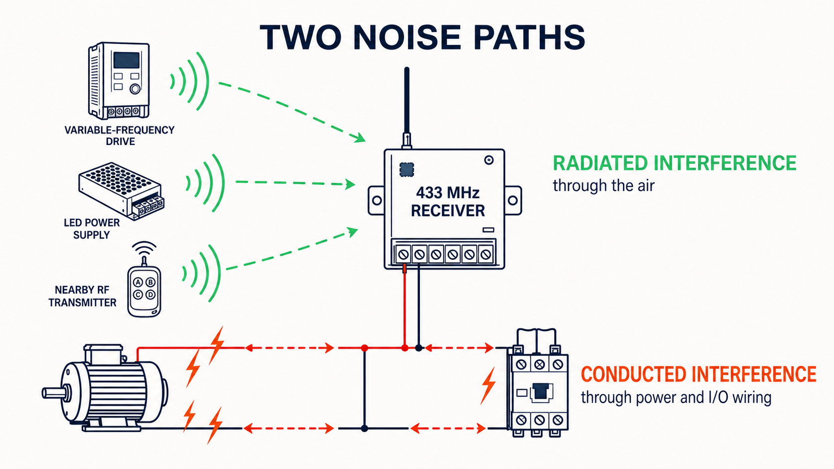
Noise can reach the receiver through the air or through its power and I/O wiring.
Engineers often look only for radio interference through the air. In control cabinets, conducted noise through the power and I/O wiring is just as common.
Radiated interference
A nearby source transmits energy that raises the receiver’s noise floor or blocks the wanted signal. The receiver may appear deaf even though the remote is transmitting normally. Separation, antenna relocation, a more selective receiver, or a different approved frequency plan can help.
Conducted interference
Noise enters through the DC supply, ground, relay contacts, or long control cables. Motors and coils are frequent causes. Fit suppression at the source: a flyback diode across a DC coil where polarity permits, or an appropriate RC snubber or surge suppressor for the actual AC or DC load. Keep noisy load current out of the receiver’s ground path and provide proper local decoupling close to the receiver.
Do not copy a suppression component from another project without checking voltage, current, switching speed, and safety requirements. The correct device depends on the load.
Check the receiver supply under real operating conditions
A receiver labelled for a wide input range may still misbehave if the supply has ripple, sharp transients, or a common return shared with a heavy load. Measure voltage at the receiver terminals, not only at the power supply. Cable resistance and shared ground paths can make the two measurements very different.
If the system fails when a relay pulls in or a solenoid starts, test with a separate regulated receiver supply. If reliability returns, redesign the power distribution rather than increasing RF power. In many installations, separating the radio electronics from the load supply is the fastest permanent fix.
A better receiver can help, but only after the installation is correct
Very simple low-cost receivers can work well in quiet locations, but their selectivity and immunity may be limited. In a crowded industrial environment, a stable superheterodyne receiver with suitable filtering generally gives more predictable results than the cheapest receiver module.
Protocol design matters too. A robust control system should validate the complete frame, reject invalid commands, and handle repeated packets deliberately. Critical motion should also have a defined safe state when communication is lost. Rolling code improves resistance to replay attacks, but it does not make an RF signal immune to electrical noise.
What I would record before contacting the supplier
Useful troubleshooting data is simple and specific:
Operating frequency and exact transmitter/receiver model.
Receiver supply voltage measured idle and while the load switches.
Load type, voltage, current, and whether it is inductive.
Enclosure material and antenna position, preferably with photos.
Reliable distance with the load disconnected and connected.
Whether the receiver indicator reacts during a failed command.
Equipment running nearby when the failure occurs.
Whether moving the receiver outside the cabinet changes the result.
“The range is bad” gives a supplier very little to work with. The information above usually separates an RF-path issue from a power, wiring, or load issue in one round of discussion.
A practical order of priority
Confirm the transmitter battery, frequency, pairing, and receiver output mode.
Test the receiver with a stable supply and the load disconnected.
Place the antenna correctly and move it outside any metal enclosure.
Reconnect the load and check for voltage dips, resets, and switching transients.
Identify nearby noise sources one at a time.
Only then consider a higher-grade receiver, external antenna, repeater, or different system architecture.
After ten years around remote-control installations, my strongest advice is still the least dramatic: make the fault repeatable before changing hardware. Once you can say “it fails only when this contactor closes” or “it works as soon as the antenna leaves the cabinet,” the problem is no longer mysterious. It becomes an engineering task with a clear next measurement.