Identify the signal interface
Describe what enters or leaves the module: a contact closure, decoded command or another documented signal. Confirm the pinout and electrical levels for the exact model before connecting it to the host circuit.
 ANRIVERSRF CONTROL
PRODUCT CATEGORY
Compact RF modules for adding wireless commands to a product or control circuit. Start with the power budget, signal interface and host logic, then choose a matched radio link.
View all productsHow to choose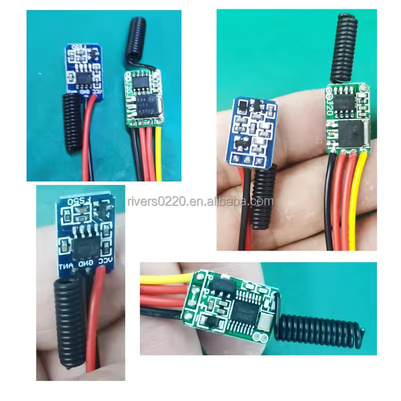
Compact learning-code RF transmitter and RE1 receiver module kit for battery-powered LED lights and embedded wireless switching. Choose 315MHz or 433.92MHz, with a DC 3.5–13V receiver and silent MOS switching up to 2A / 20W.

A long-range 315/433 MHz wireless transmitter module for converting wired normally-open or normally-closed signals into RF control signals for alarm systems, door contacts, lamps and automation devices.

Compact learning-code RF transmitter module for battery-powered wireless controls, alarm systems and embedded switching applications.

Long-standby 315/433.92 MHz RF receiver and remote control system with sleep mode, designed for battery-powered devices and DC 3.5–12V applications.

DC 12–24V wireless alarm transmitter module with 315/433.92 MHz options, dry-contact triggering, and 200 m or 1000 m open-area range versions.

Compact 315/433.92 MHz learning-code RF receiver and two-button remote set for battery-powered LED lighting and low-voltage smart control applications.
SELECTION GUIDE
A module gives you a building block to integrate. It may transmit a contact trigger, receive a supported code or pass a signal to another controller. These functions are not interchangeable. Define which tasks belong to the RF hardware and which remain with your product’s electronics.
Describe what enters or leaves the module: a contact closure, decoded command or another documented signal. Confirm the pinout and electrical levels for the exact model before connecting it to the host circuit.
For a battery product, specify the supply, expected standby time and command frequency. Check receive, transmit and sleep behavior where applicable, including how the device wakes and how quickly it must respond.
Provide the available board space and enclosure material early. Leave room for the documented antenna arrangement and validate the link with the final housing, wiring and power supply in place.
PRODUCT COMPARISON
Use the listed specifications to shortlist a starting point. Open the product page for the full configuration and confirm any unlisted requirement with us.
| Product / model | Frequency | Supply | Coding / interface |
|---|---|---|---|
| RE1 Micro RF Transmitter & Receiver Switch KitRE1 | Frequency options: 315MHz / 433.92MHz | Receiver supply voltage: DC 3.5–13VTransmitter supply voltage: DC 3–12V | Code type: Learning code; EV1527 transmitter |
| 1km 433MHz Wireless Transmitter and Receiver ModuleRF1000 | Frequency: 433.92 MHz / 315 MHz | Input Voltage: DC 12 V-24 VSupply Ability: 100000 sets per month | Code Type: Fixed Code / Learning CodeTrigger Signal: Power-on trigger / dry-contact flip trigger / high-level trigger |
| RF 433/315 MHz Micro Transmitter ModuleRF1 | Frequency: 433.92 MHz / 315 MHz | Input voltage: DC 2–12 V | Code type: Learning code |
| R16 Low-Power Sleep Mode RF Receiver Module & RemoteR16 & MOTOR | Frequency: 433.92 MHz / 315 MHz | Receiver power supply: DC 3.5–12V | Encoding: Learning code |
| RF1000 Long-Range Wireless Alarm Signal Transmitter ModuleRF1000 | Operating frequency: 433.92 MHz / 315 MHz | Input voltage: DC 12–24V | Trigger methods: Power-on / dry-contact flip / high-levelCompatible codes: PT2262 / PT2264 / SC2262 / EV1527 |
| Mini Low-Voltage RF Receiver Module for Battery-Powered LED LightsJ20 & R16-E1 | Frequency: 433.92 MHz / 315 MHz | Power supply: DC 3.5–13 V | Encoding: Learning code |
APPLICATION FIT
A contact-triggered transmitter can form the wireless part of an alarm interface when its input requirements match the source. A receiver module may suit a compact lighting or battery product when its output and power behavior fit the design. For direct load switching, also compare the ready-made relay receiver range.
Explore RF control applications ↗OEM & CUSTOMIZATION
Send a block diagram, the interface requirements and the target power budget. We can review a module and matching transmitter or receiver against the design. Include your intended sales markets and the final enclosure when discussing validation requirements.
See our customization capabilities ↗BEFORE YOU SPECIFY
Choose around the interface you need. A relay receiver can provide a switching interface; a module is a candidate when you are integrating the wireless function into your own electronics. Verify the exact outputs and control responsibilities for each option.
No. Battery life and response time depend on the complete operating cycle. Specify how often commands arrive and how long the product can wait for a response, then evaluate the selected module in that cycle.
Frequency alone is insufficient. The transmitter and receiver must agree on the supported signal and code format. Select a documented combination and test the command path through the complete host product.
COMPLETE THE SYSTEM
LET’S SPECIFY YOUR SYSTEM
A clear starting brief makes the first configuration easier to review.