
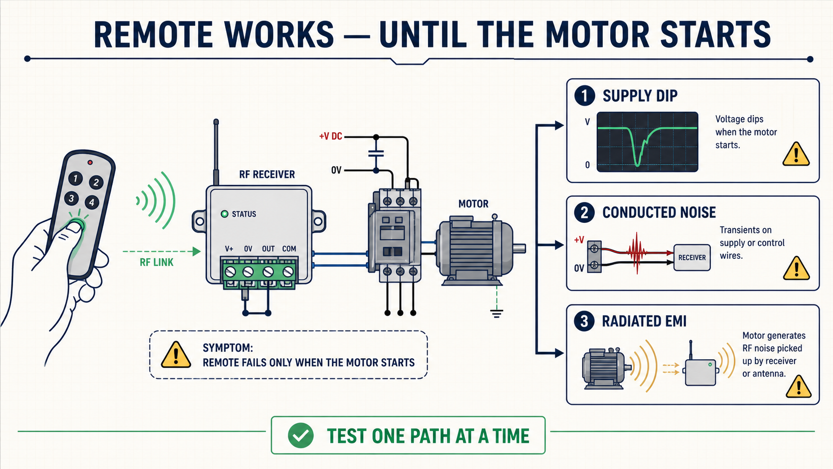
Short answer: if an RF remote works perfectly with the motor stopped but becomes intermittent the moment the motor starts, the radio is often not the root cause. The usual causes are a supply dip, conducted noise returning through the power wiring, or radiated noise from the motor and its cables. Treat those as three separate faults. If you change antennas before separating them, you can spend an afternoon fixing the wrong problem.
I have seen this pattern on gates, winches, pumps, linear actuators, small cranes, and battery-powered machinery. The bench test passes. The receiver switches cleanly from across the workshop. Then the controller is installed beside the contactor or motor driver, and the customer reports that the range has “collapsed.” What changed was not the radio specification. What changed was the electrical environment.
Field note: do the first comparison with the cabinet, antenna and cable routing exactly as the operator uses them. An open cabinet door can hide a marginal installation.
Start with the timing of the failure
The most useful question is not “How far does it work?” It is “Exactly when does it fail?” That one detail quickly divides the problem into useful branches.
It misses the first command when the motor starts: suspect supply sag, contactor-coil noise, or a reset of the RF receiver.
It works at startup but drops commands while the motor is running: suspect broadband radiated noise, brushed-motor commutation, or PWM motor cables.
It releases late or chatters when the button is held: suspect repeated packet loss near the receiver sensitivity limit, sometimes combined with a poorly chosen output mode.
It fails only when the motor stops: suspect the inductive turn-off transient from the motor, brake, solenoid, or contactor coil.
Write the timing down before moving any wire. In field troubleshooting, a precise symptom is worth more than ten random component substitutions.
Fault 1: the receiver supply is dipping
Small RF receivers are often powered from the same 12 V or 24 V source as a motor, actuator, or contactor circuit. On a multimeter, the voltage may look normal because the dip lasts only a few milliseconds. The receiver, however, can reset in less time than the meter needs to update.
A brushed DC motor may draw several times its running current at startup. A contactor coil can also pull the control rail down if the supply is marginal or the cable run is long. If the receiver microcontroller browns out, the LED may blink and the relay may release, but the event can be too fast to notice.
A quick isolation test
Power the RF receiver from a separate, known-good supply while keeping the output electrically isolated from the motor circuit.
Run the same start, stop, forward, and reverse sequence.
If the fault disappears, stop investigating the antenna. Measure the original rail at the receiver terminals with an oscilloscope or a meter that can capture minimum voltage.
Measure at the receiver, not only at the power supply. Cable resistance, undersized connectors, and shared ground paths can create a local dip that is invisible at the source.
Typical corrections
Use a supply with enough transient current margin.
Separate receiver power from the motor power path, or add a properly rated DC-DC stage.
Add local bulk capacitance and high-frequency decoupling at the receiver, following the receiver manufacturer’s limits.
Use a star return so motor current does not flow through the receiver ground conductor.
Check crimp quality and terminal resistance; a connector that looks clean can still lose a volt under surge current.
Fault 2: noise is coming through the wires
Conducted noise enters through the power input, relay contacts, control lines, or a shared ground. It is especially common when a relay receiver drives a contactor coil, solenoid valve, brake, or DC motor without suppression at the load.
The suppression device belongs close to the noise source. Putting it beside the receiver leaves the long cable free to act as an antenna.
For a DC coil, a flyback diode is effective when slow release is acceptable. Confirm polarity.
When faster release is required, use a TVS diode or a diode-plus-Zener arrangement selected for the coil voltage and energy.
For an AC coil, use an RC snubber or suitable MOV rated for the application.
For a brushed DC motor, use the motor manufacturer’s recommended capacitor or suppression network and keep the connection leads short.
Do not choose suppression parts only by nominal voltage. Repetitive energy, temperature, release time, and failure mode matter. A diode that protects the electronics but makes a safety brake release too slowly is not a good fix.
Fault 3: the motor system is radiating into the receiver
Brushed motors generate noise at the commutator. PWM drives add fast voltage edges. Long motor leads turn those edges into an efficient radiator. The receiver antenna and its first RF amplifier are designed to detect very small signals, so placing them a few centimeters from a motor cable is asking them to work in the worst part of the cabinet.
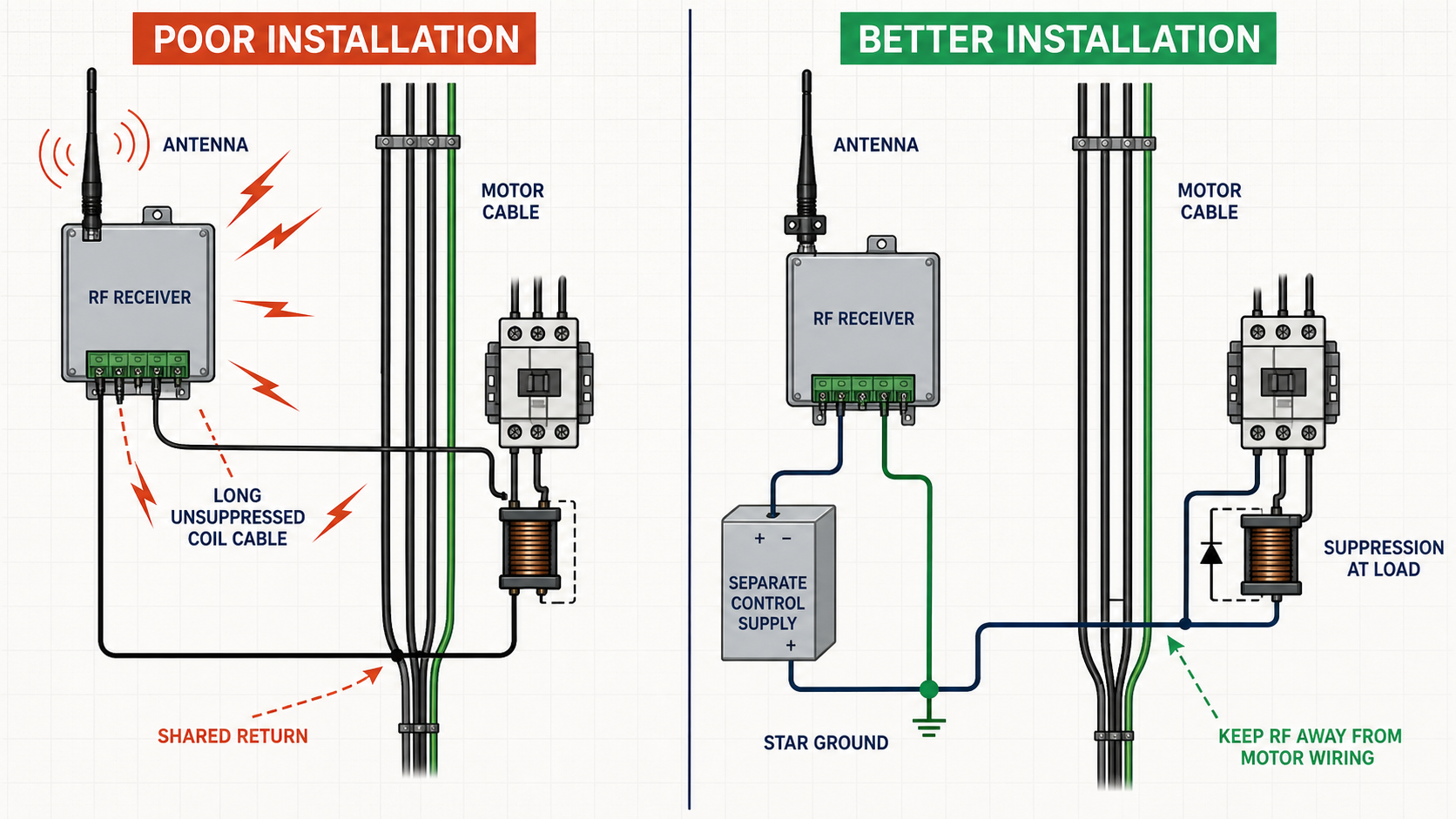
Figure 2. Separate the RF receiver from motor wiring, keep suppression close to the load, and prevent motor current from sharing the receiver return path.
What to change before changing the radio
Move the receiver and antenna away from the motor, VFD, contactor, relay bundle, and high-current cable loop.
Route antenna wiring and low-voltage control wiring separately from motor wiring. Avoid long parallel runs.
Cross noisy cables at roughly 90 degrees when separation is not possible.
Keep the antenna outside a closed metal enclosure, or use a correctly mounted external antenna with the specified feedline.
Do not coil excess antenna cable beside the motor controller.
Bond and shield according to the drive manufacturer’s instructions; a shield connected in the wrong place can make common-mode current worse.
A useful field test is temporary distance. With power isolated, relocate the receiver or extend only the low-energy control connection so the receiver sits one or two metres away from the motor equipment. If reliability returns, you have strong evidence of coupling or cabinet placement rather than a defective transmitter.
Use a test sequence that produces evidence
Random button pressing produces anecdotes. A controlled sequence produces a diagnosis. I normally use the following order:
Receiver only: verify operation with the load disconnected.
Load connected but stationary: confirm wiring and output logic.
Independent receiver supply: separate power integrity from RF behavior.
Suppressed load: add the correct device at the coil or motor and repeat.
Temporary separation: move the antenna and receiver away from noisy cables.
Worst-case run: test at low battery voltage, maximum motor load, closed cabinet doors, and the actual operator position.
Change one variable at a time and record at least 20 to 30 operations per condition. A single successful press is not proof. For hold-to-run systems, test long holds, short taps, direction changes, and emergency release behavior.
Do not mask an electrical problem with more RF power
A higher-power transmitter or longer-range receiver may appear to solve the issue because it improves link margin. Sometimes that is a valid design choice, but it should come after the electrical problem is understood. More link budget does not stop a receiver from rebooting, and it does not protect relay contacts from an unsuppressed coil.
The durable solution usually combines three things: a stable receiver supply, suppression at the load, and sensible physical separation. Once those are correct, antenna choice and radio sensitivity become meaningful engineering decisions instead of guesses.
Information to collect before asking for support
If you want a supplier or engineer to diagnose the problem quickly, send the following details:
Receiver input voltage and measured minimum voltage during motor start.
Motor or coil voltage, running current, and startup or stall current if known.
Load type: brushed DC motor, AC motor, solenoid, contactor, brake, or electronic driver.
Suppression components already fitted and where they are physically installed.
A photo showing receiver, antenna, power supply, motor driver, and cable routing.
The exact event that causes failure: start, continuous running, reversing, or stopping.
Whether a separate receiver supply changes the result.
Those seven items usually narrow the fault faster than a range figure alone. The lesson from the field is simple: when the remote fails only under load, test the power and noise paths before blaming the air link.