
Most receiver failures I see are not RF failures at all. The remote pairs correctly, the relay clicks, and then the board stops working as soon as it is connected to the machine. In many cases, the cause is simple: a dry-contact output was treated as a voltage output, or an already powered output was connected to a second supply.
The markings beside the terminal block do not always make this obvious. COM, NO and NC describe the switching path, but they do not tell you whether voltage is present. Before connecting a lock, motor contactor, gate controller or lamp, spend five minutes identifying the output. It is cheaper than replacing the receiver and usually faster than troubleshooting the installation later.
Start with the output type, not the load
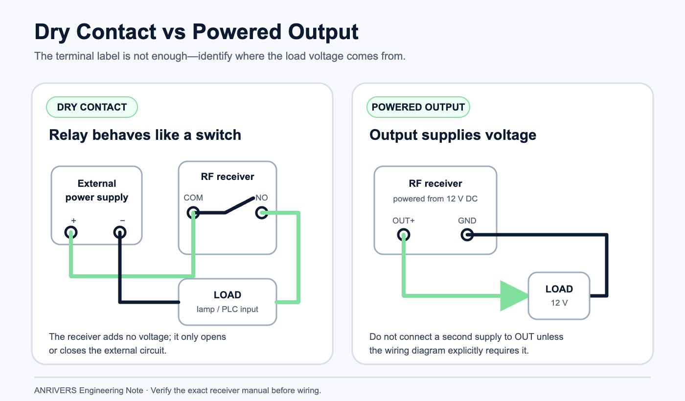
A dry-contact output is simply an electrically isolated switch. The receiver energizes a relay, and the relay joins COM to NO or COM to NC. The contact does not create 12 V, 24 V or mains voltage by itself. You provide the circuit voltage from the equipment side, and the relay only opens or closes that path.
A powered output is different. When the channel turns on, the output terminal supplies a voltage referenced to the receiver ground or neutral. Depending on the design, this may be a positive DC output, a low-side transistor output, or a switched AC line. Connecting an external supply to that terminal can put two sources against each other and damage the output stage.
The important habit is to stop treating every terminal marked “OUT” as the same thing. Read the wiring diagram for the exact model. If the diagram is missing or unclear, verify the terminal with a meter before attaching the load.
How to identify the output with a multimeter
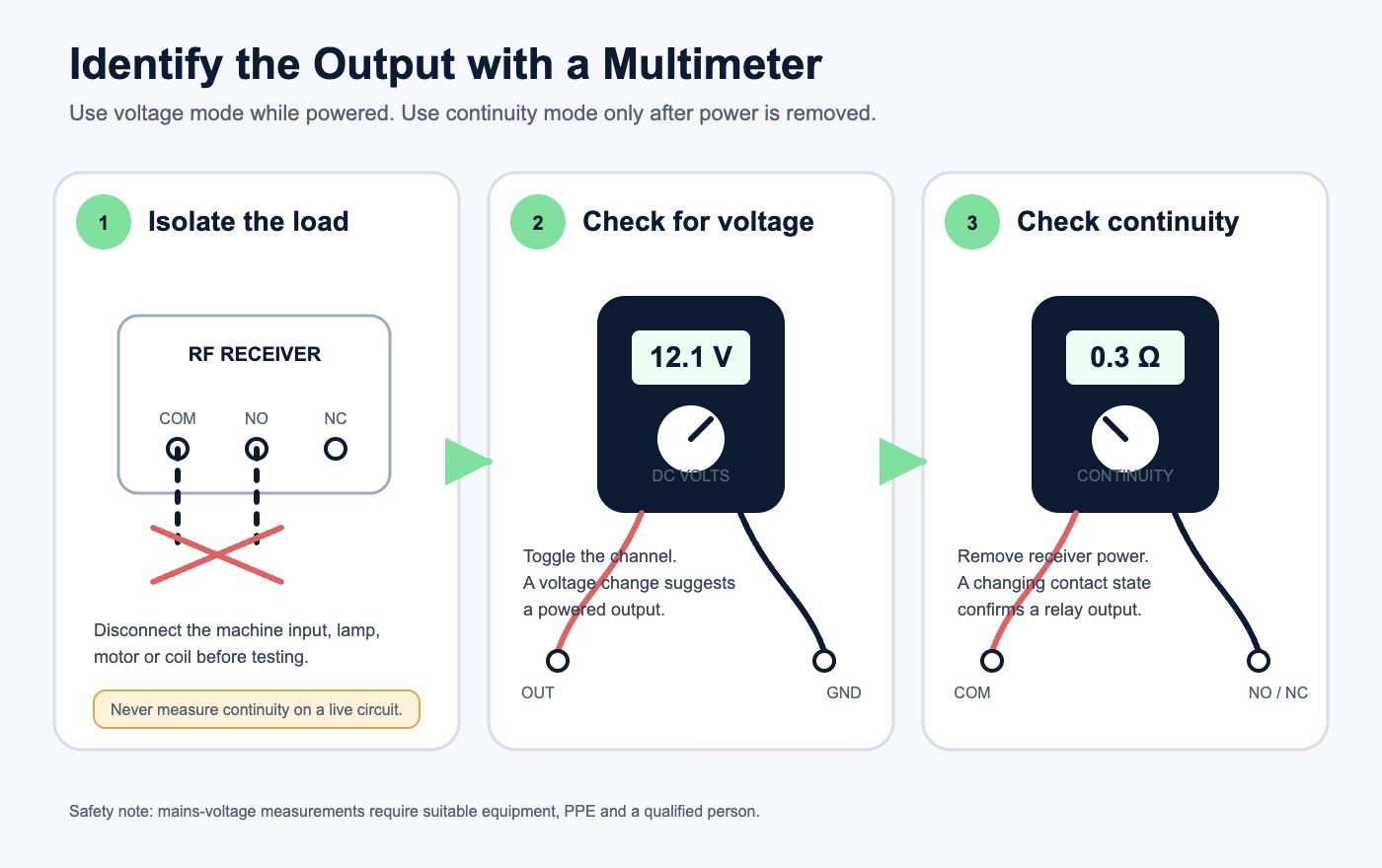
Disconnect the load first. Power the receiver from the specified input and set the multimeter to DC voltage. Measure between the suspected output and the receiver negative terminal with the channel both off and on. For an AC receiver, repeat the check with the meter on the correct AC range and use proper precautions; if you are not qualified to work on mains wiring, stop and have an electrician make the measurement.
If a terminal changes from approximately 0 V to the rated supply voltage when the relay operates, it is probably a powered output. If COM, NO and NC show no useful voltage to the receiver negative terminal, switch the meter to continuity mode only after removing power. COM-to-NC should normally be closed while COM-to-NO is open. When the relay is energized, those states reverse.
One caution from the field: a continuity beep proves that a contact closes, but it does not prove that the contact is suitable for the load. Voltage, steady current, inrush current and load type still need to be checked against the relay specification.
What COM, NO and NC mean in a real circuit
COM is the moving contact. NO, or normally open, connects to COM only when the relay is energized. NC, or normally closed, connects to COM while the relay is idle. “Normal” refers to the relay coil with no power, not to the state you would prefer the machine to have.
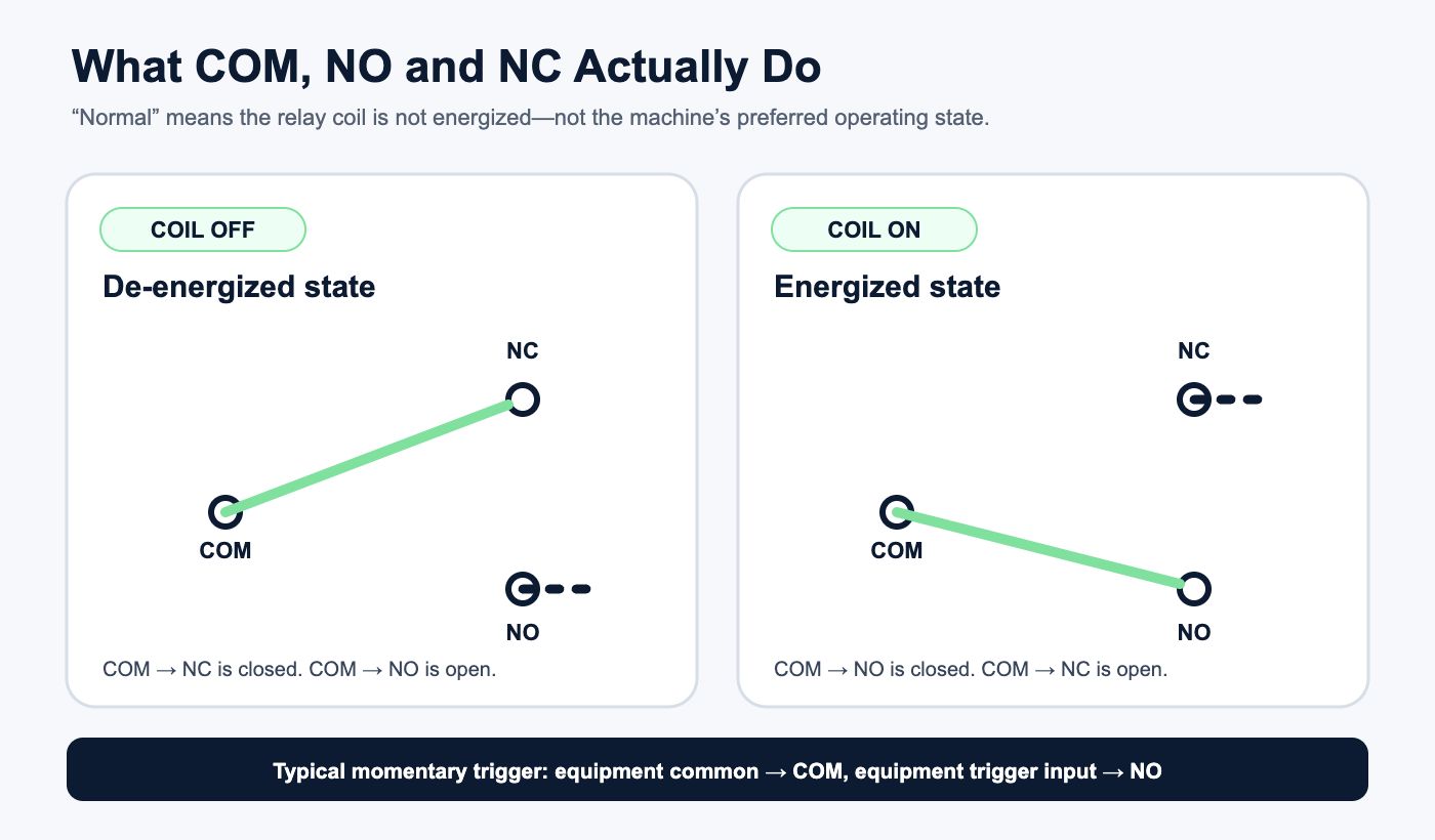
For a gate-controller push-button input, the common arrangement is to wire the controller’s button common to COM and its trigger input to NO. The receiver then imitates a short button press. No extra voltage should be injected into the controller input unless its manual specifically asks for one.
For a lamp or solenoid, the supply is usually routed through COM and NO so the load is off at rest. NC is useful for a circuit that must remain closed until an alarm or fault occurs, but think carefully about what happens if the receiver loses power. A fail-safe function depends on the whole system design, not only on choosing NC.
Four wiring mistakes that cause most failures
The first is feeding voltage into a dry contact as though COM were the receiver’s power input. COM belongs to the relay contact set; it is not automatically positive, negative or neutral. On many boards the receiver power terminals are completely separate.
The second is tying together supplies that should remain isolated. A 12 V receiver may control a 24 V PLC input through its relay contacts, but the two supply positives should not be joined unless the system design calls for a common reference. The relay isolation is often the reason that interface works safely.
The third is switching a motor, pump or large solenoid directly from a small onboard relay. These loads have high starting or inductive current. Even when the running current looks acceptable, the first few milliseconds can weld the contacts or reset the receiver. Use the RF receiver to drive a correctly rated contactor or interposing relay when the load is beyond the board’s practical capacity.
The fourth is ignoring transient suppression. A DC coil should normally have a flyback diode or a suitable TVS device, with polarity checked. An AC coil usually needs an RC snubber or MOV selected for the circuit. Place the suppression device close to the load, not several meters away at the receiver. This small detail prevents many intermittent resets and unexplained re-pairing complaints.
Do not assume relay isolation means the whole board is isolated
The relay contacts may be galvanically isolated from the receiver electronics, but clearances, connector spacing and enclosure construction still limit what can be switched safely. A compact board that accepts 12 V DC power is not automatically suitable for switching 230 V AC just because the relay case carries a high voltage marking.
For mains circuits, check the complete product rating, PCB creepage and clearance, terminal rating, enclosure, fuse protection and applicable local standards. If the documentation only gives a relay component rating and says nothing about the assembled controller, treat that as a warning sign. In industrial work I prefer to keep mains power in a certified contactor circuit and let the RF receiver handle only the low-voltage coil or control input.
A five-minute pre-power checklist
Confirm the receiver input voltage and polarity.
Identify whether each output is dry contact, powered voltage, open collector or another transistor type.
Trace COM, NO and NC against the actual equipment diagram instead of relying on wire color.
Check load voltage, steady current and inrush current; add an interposing relay or contactor where needed.
Install suitable suppression on coils and other inductive loads.
Fuse the supply and make the first test with the final load disconnected.
The practical rule I use
When I receive an unfamiliar RF controller, I treat every output terminal as unknown until the diagram and meter agree. I test it on the bench with a small indicator load, then connect the machine interface, and only after that energize the real load. This order feels slower when a project is waiting, but it usually saves time because each step isolates one possible mistake.
If you are selecting a receiver for an existing machine, send the equipment wiring diagram, control voltage, load type, current and required operating mode before ordering. Those details are enough to determine whether you need dry contacts, a powered output or an external contactor—and they prevent most of the expensive surprises that appear during commissioning.